I find that it’s theraputic to reflect on previous creative ventures. While I’d like to believe that I’m driven to reinforce lessons learned, I admit that it’s moreso to satisfy my nostalgic tendencies. It’s possible to see the ebb and flow of code through version control, but it isn’t visceral like hardware is, well, I keep telling myself that. Admittedly I’m very hardware-centric, though I believe that that there’s a special kind of learning which is enabled through hardware integration and the unavoidable iterative deisgn process. How my learned lessons manifest themselves takes the form of a narrative. Imagery and rhetoric act as memory markers. From the way that the plastic sheath on an aluminum polymer capacitor burns and wicks away from where a hot iron sloppily brushes by it, to the latent smell and residue of solder flux adorning the footprint of an LQFP part; to me it engenders the same feelings of frustration and curiousity that I felt in the moment in a way that forces me to relive my failures and successes. Those feelings make concrete the issues that forced me to twist my mind around my own process in a way that typing ‘git log –stat’ never can. It’s in those hours and soldering iron knuckle scars that I remember the wonder I felt at the perceived complexities of analog hardware design, the black magic of high-speed digital logic design, and sometimes how even the most simple of components can cause amazingly complex integration problems. Most of the hardware projects I’ll list here were born of my curiousity and desire to learn (Is that silly to say? Do people embark on creative ventures out of the desire to perpetuate ignorance?), and I’ll describe them in the way that comes most naturally to me in the immediate moment of reflection.
I’ve spent a lot of time on making big copper things spin very precisely, so I should probably start with all of the fun stuff associated with it. Beyond my PMSMx brushless motor drivers being my most long-lived and supported project, it was through this project that I cut my teeth on PCB design and completed my first board spin.
It all started with a SN7544 on a breadboard mess.
BLDC SN7544 TEST - OLD from pavlo manovi on Vimeo.
While it was ugly, it worked. It worked well enough for me to get a PCB run made. After laying it out, waiting a week for it to show up, and trimming the boards, it surprisingly worked on the first try, a very costly problem. While it worked, if I had been given the schematic capture for the board today, I would have pointed out that it wouldn’t continue to work well for long. At the time I didn’t really understand how to work with MOSFETs with large gate capacitances and how things like trace impedances could cause issues with how the gates to the FETs behave. It didn’t help that the MOSFET pre-driver I was using was very picky about how its analog ground plane was set up, a concept I had no real understanding of at the time. It worked, but it would soon help me to appreciate just how heavy the two words ‘hardware’ and ‘debugging’ can feel when used in conjunction.
BLDC Test 2 from pavlo manovi on Vimeo.
The firmware at this point was very simple, a block commutation scheme, so 60 degree commutation. Actually learning how motors work and sophisticated ways of driving them filled many other hours that are more appropriate to talk about in a different, less hardware-centric post. Back to the hardware, there were a few more failed attempts at making the board smaller while still maintaining operability with one of my colleague’s CAN capable micro-controller boards before I ended up moving to a more integrated solution.
It was at this point that I was approached to create a motor driver for a robotics application that had some very specific design requirements which lead to some cool power constraints. This was my first consulting gig, and my first attempt at approaching board manufacturing and the logistical problems associated with it, e.g. part procurement, cost scaling, export law, etc. I even ended up making a little spreadsheet to help understand how all of these costs changed over time. This sheet didn’t keep up with the changes in the design for more than a couple weeks, but it did help me to foster an intuition as to what the wrong thing to do was in terms of choosing parts.
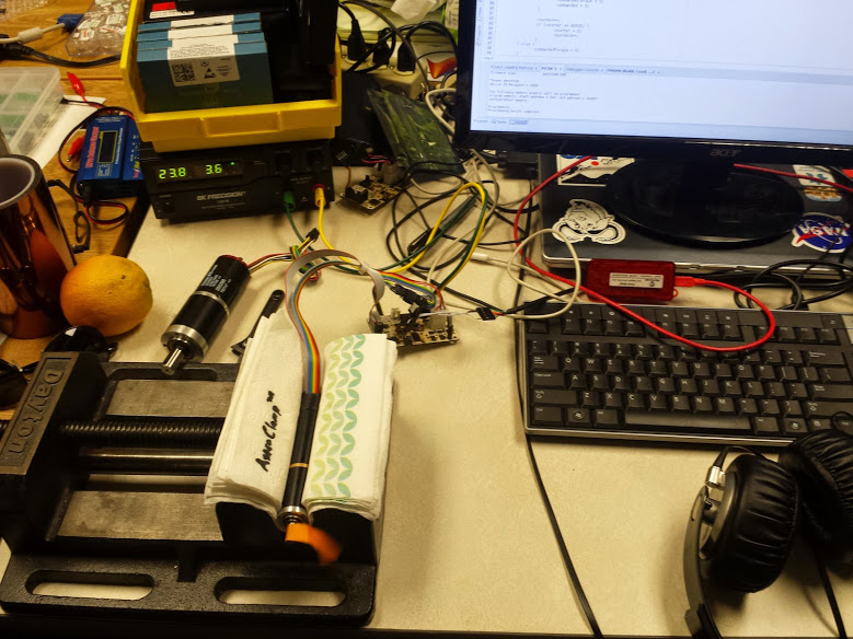
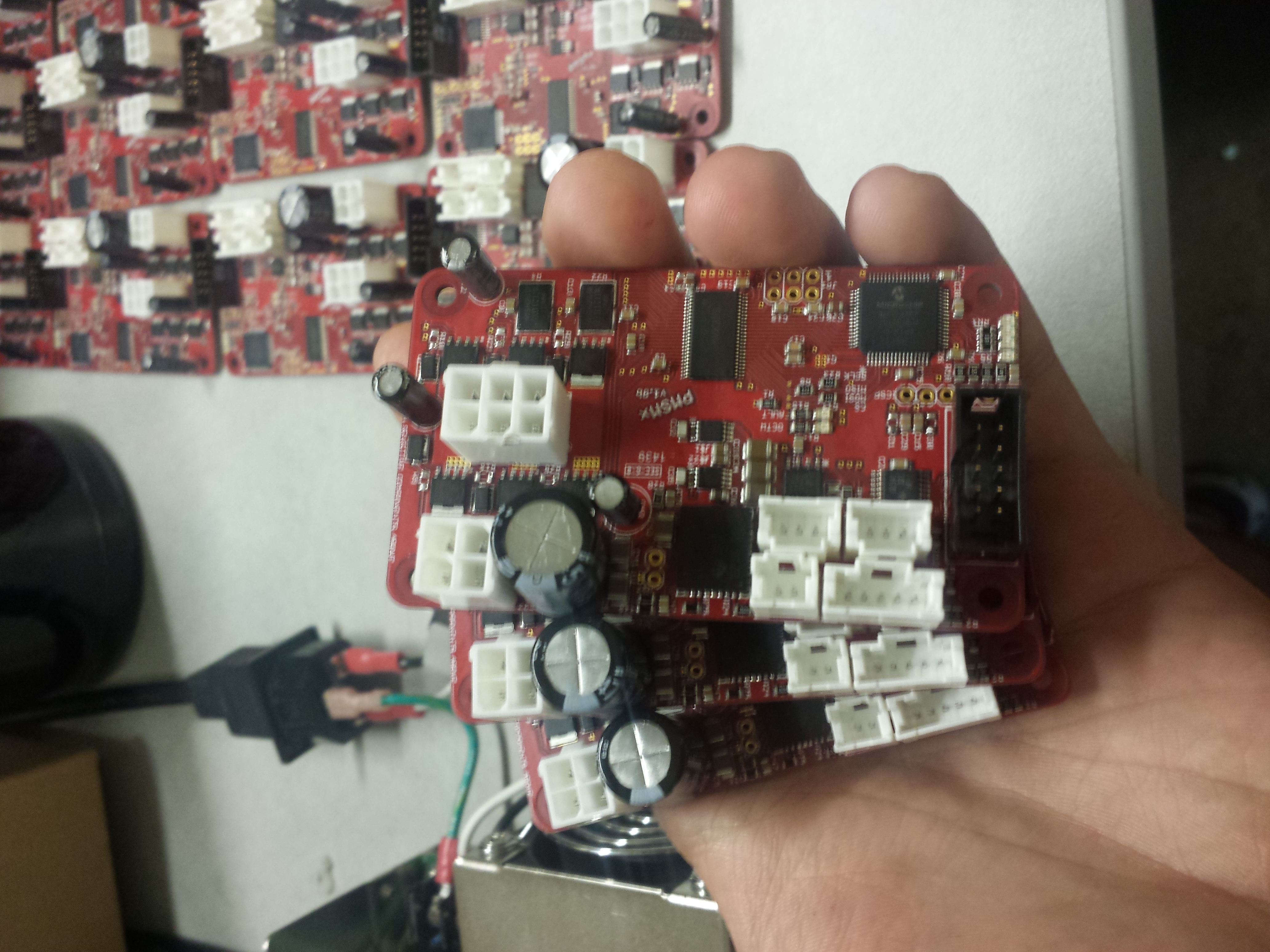
Soon we were working on really nice Maxon synchronous machine motors and I found myself quite deep down in a rabbit hole. Suddenly math, suddenly controls, suddenly science. There were so many ways of doing things wrong, and I probably found most of them. I went through five board runs where things waffled between working, and not working, where problems went away only for others to show up. It was a frustrating time, but I learned to fully internalize reference designs, that you can actually contact the engineers who designed the reference layouts and the chips themselves (yes, they’re real people), and that the reference designs and documentation can often be wrong. Eventually the design converged towards a single overall design which I foolishly decided to get with a white solder-mask.
After reflowing them in our reflow-oven-of-dubious-quality with what we thought to be the right reflow profile, we found that the boards ended up always turning from white into a charming color somewhere between latte and burnt-marshmallow. These boards ended up supporting most of the controls work and systems integration throughout my 2014 summer internship at NASA Ames. The sheer amount of abuse that these boards put up with and survived was absolutely ridiculous, I was so proud of them that when they finally ended up giving up after a few months of figuring out how to correctly dump hundreds of watts through them that I almost teared up. Experimenting with field-oriented-control on these boards was harsh, though System-ID with them was especially brutal, here’s a photo of the board at it’s brownest, a mixture of coffee-spills, over-heating, reflow discoloration, and flux residue. Some supporting hardware like The AstroClamp(tm) was used to hold the motors during the ID process, and was supplemented by the AstroSHHHHH(tm), a sophisticated cardboard box full of foam that we put over the thing to try and quiet it down with while I gathered data from the motors for hours. I’ll try to find some photos of them and update this post withthem at some point.
Eventually I got twenty of them produced. It took way longer than the board-house said it would, and each one required that I modify the boards. The board house was mostly at fault, though given the experience that I have now, and also considering that we didn’t have a post-production-test for them to run, board failures and incorrectly assembled boards was to be expected. It was at this point that things felt pretty good, and the design reached steady-state. While the code continued to evolve, the hardware was finally good enough.
About half-way through the process of designing the PMSM board, I got involved in an interesting data-science project that I thought my hardware-comfort could improve. Enter SEADS. Smart energy analysis and disaggregation. The goals of this project required a low-cost flexible data gathering interface for current and voltage measurements sampled continuously, with some ability for pre-processing and transmission over various physical layers. While the data itself is fairly straightforward to sample and process, the goal of disaggregation of loads by spectral energy signatures required rich input across the entirety of the nyquist bandwidth of the acquisition system. As such, I experimented extensively with various multi-stage filtering topologies with the intention of separating spectral bandwidths and using separate automatic gain controlled amplifiers to try and maximize the signal to noise ratio of the current and voltage measurements over that specific band. This made sense as there’s precedent to the idea that with regards to higher frequency spectral energy induced by appliances and loads operating, the normalized amplitude in relation to the other harmonic frequencies drops off considerably, though harmonics specific to those devices do exist.
The first system consisted of a big TI ADC with bipolar voltage input of -15 to +15v with some very nice low noise LDOs. This system worked out well, though didn’t provide the return on component cost and system complexity that I was expecting, so I moved to a more traditional current and voltage sampling method focusing on low-cost invloving an FT2232H to handle the USB stack and a little bit of buffering, a pic32 and a 24-bit sigma-delta adc for sampling signals from an iron-core current transfortmer, or rogowski coil with an integrator circuit. This system yielded itself well to experimentation and ended up creating a system capable of checksumming and transferring data at a rate of ~2MB/s from four current/voltage channels.
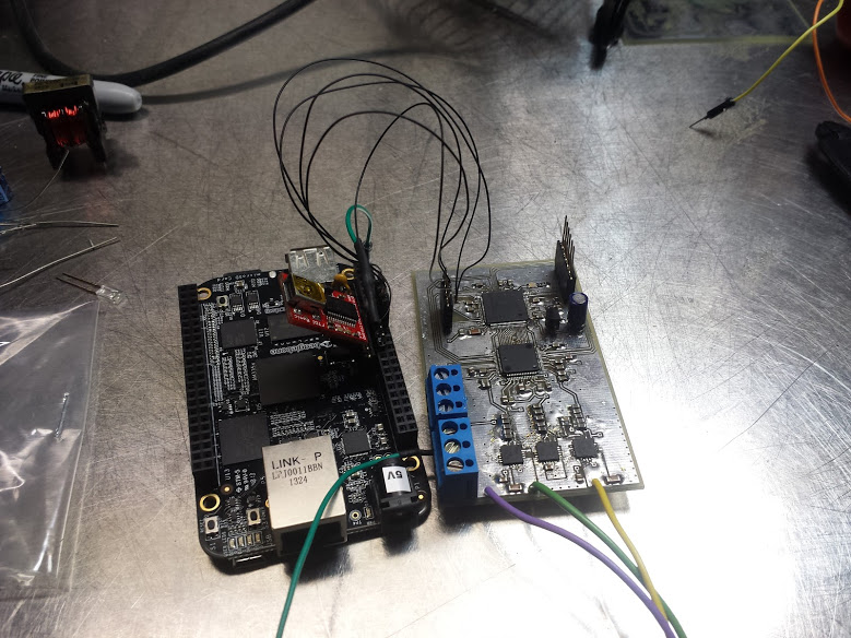
I also made a slightly different design that combined everyone’s favorite IOT thing, the ESP8266, to transmit data to the SEAD team (our team’s) restful API that handled storing usage data, and visualizing it by device, among a multitude of other wonderful useful things.
– Picture of the SEAD.IO GUI
Originally I thought that the iron core transformers would end up being a limiting factor for the system as supposedly the bandwidth of the transformers is very low, though testing them while dog-fooding the system showed that they were fine, a process that I talked about in a previous post (link to it here).
Along the way I also made a whole bunch of other hardware boards. This is where I’ll diverge from any real narrative to a system where I’ll just list in the order that I either find pictures, or pull them from a box.
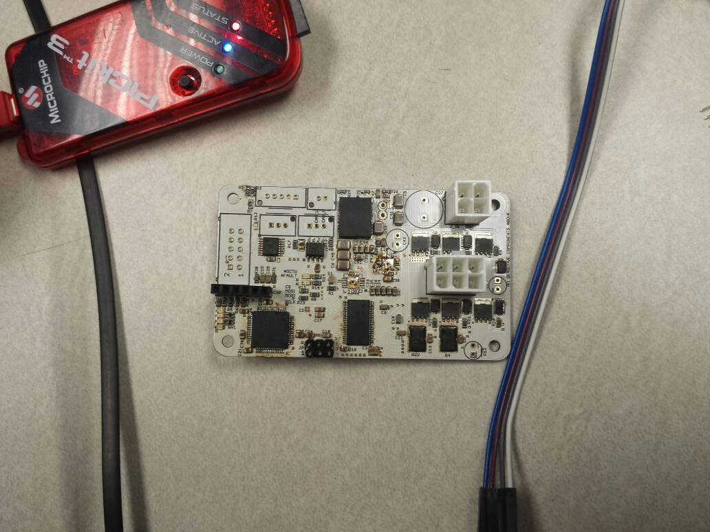
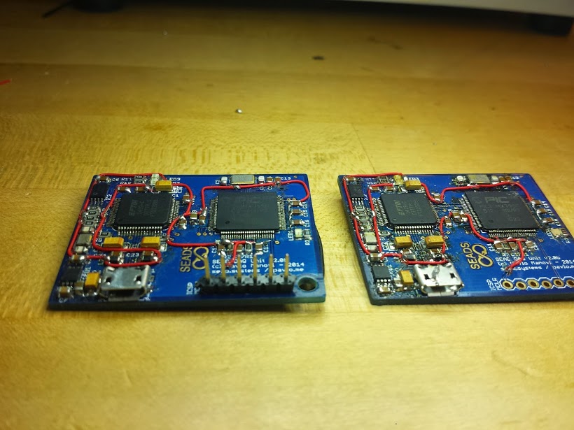
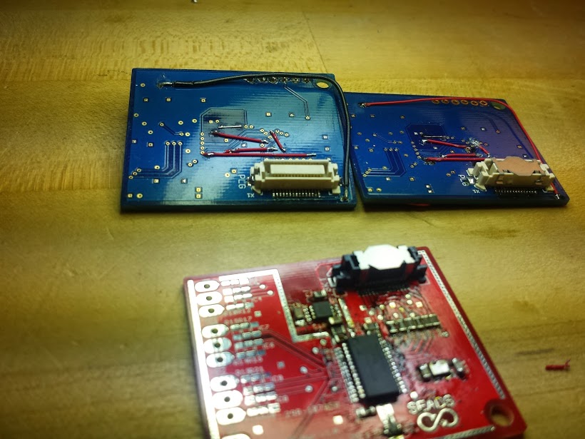
Here’s a lesson I learned about triple checking the gerbers that you actually send to the board house. It turns out that if you make the 2 inner-layers of a four layer board the same, that you have to do a whole bunch of soldering to get it to work while you wait for a new board spin to be fininshed.
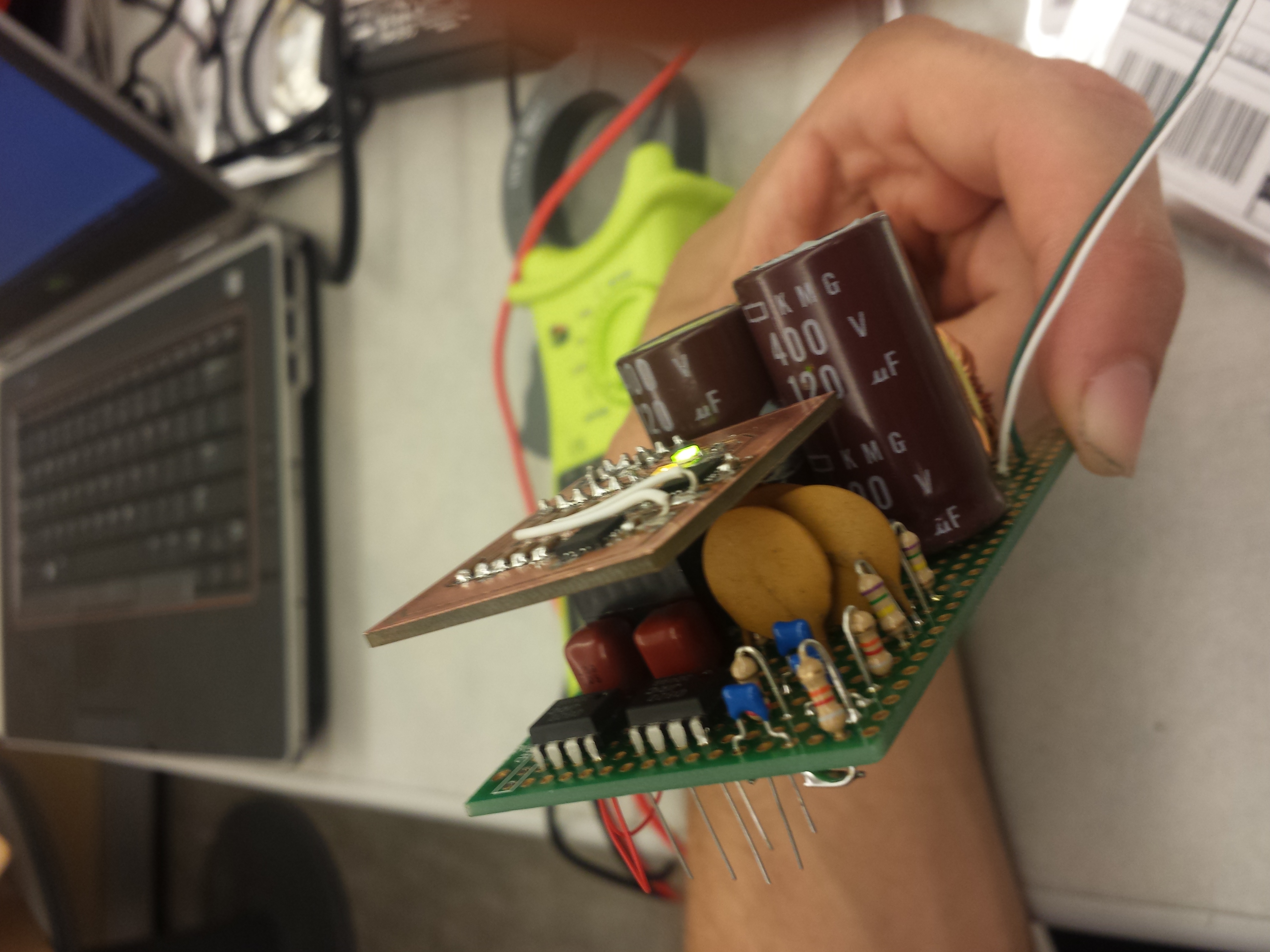
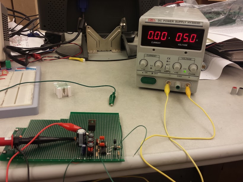
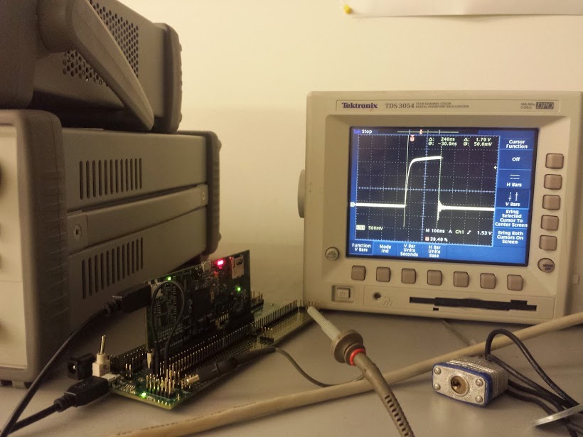
Here’s where I learned just how scary it is when you flip a sign while doing the calculations for boost regulator and all of a sudden you have something that’s pumping out over 300 volts from a 5 volt sourse.
It turns out that sensorless field oriented control by current measurement and classic clarke-parke inv/non-inv transforms and a sliding mode controller on rotor flux can’t run on a ten year old pic. Chalk this one up to not fully understanding the computational and sensor requirements of a control system before designing it.
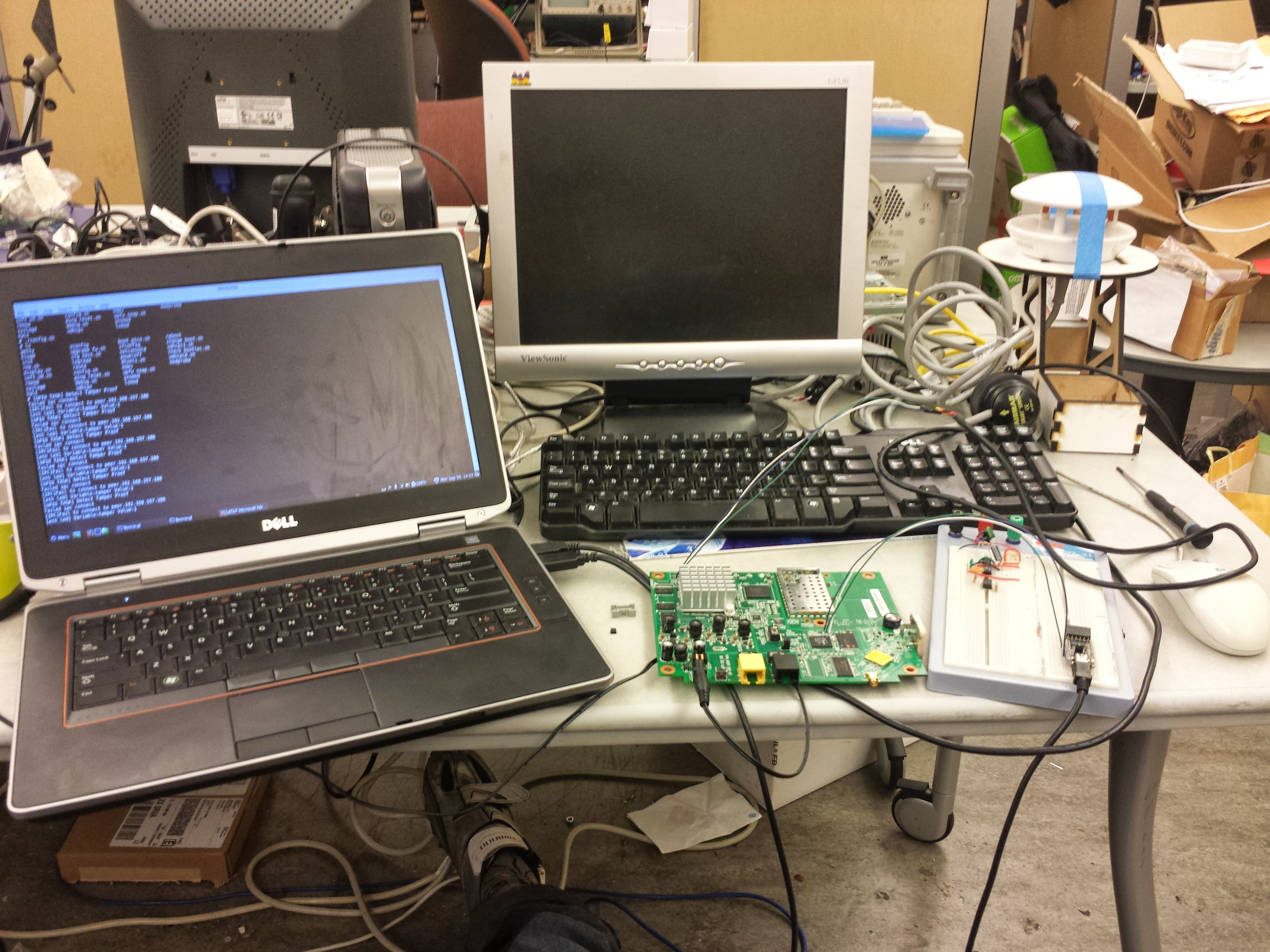
I learned about to what lengths engineers will go to include anti-tamper systems in this project where I was trying to spoof a GPS signal for a micro-tower. While I got into the shell and ended up getting root access, there was some interesting ROM/fuse stuff going on which prevented it from working after it was opened up, very cool.
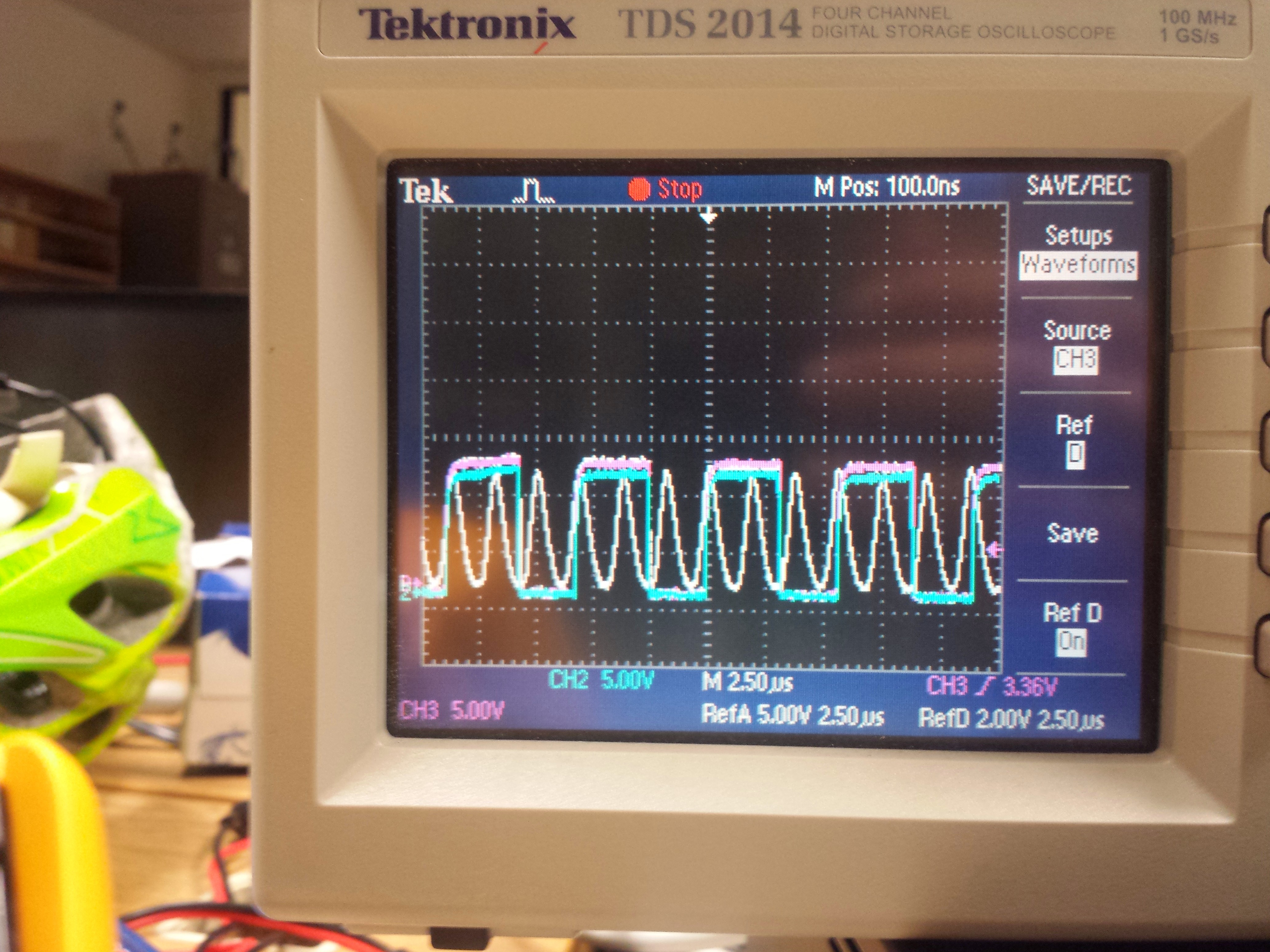
This photo represents my love-hate for some of TI’s processor architectures. This was a dual-core Delfino F28377D microcontroller with some awesome analog hardware and DSP functionality. Here I was testing the computation time of an FFT operation by toggling a pin before and after the function call. This chip was really good at a lot of things, but they really phoned it in on the processor design making the second core basically required to handle all the stuff that a DMA engine or a really good interrupt handling system should take care of. Based off the support, documentation, and code that I ended up writing for this microcontroller, I probably won’t end up using it or a C2000 based system for a while.
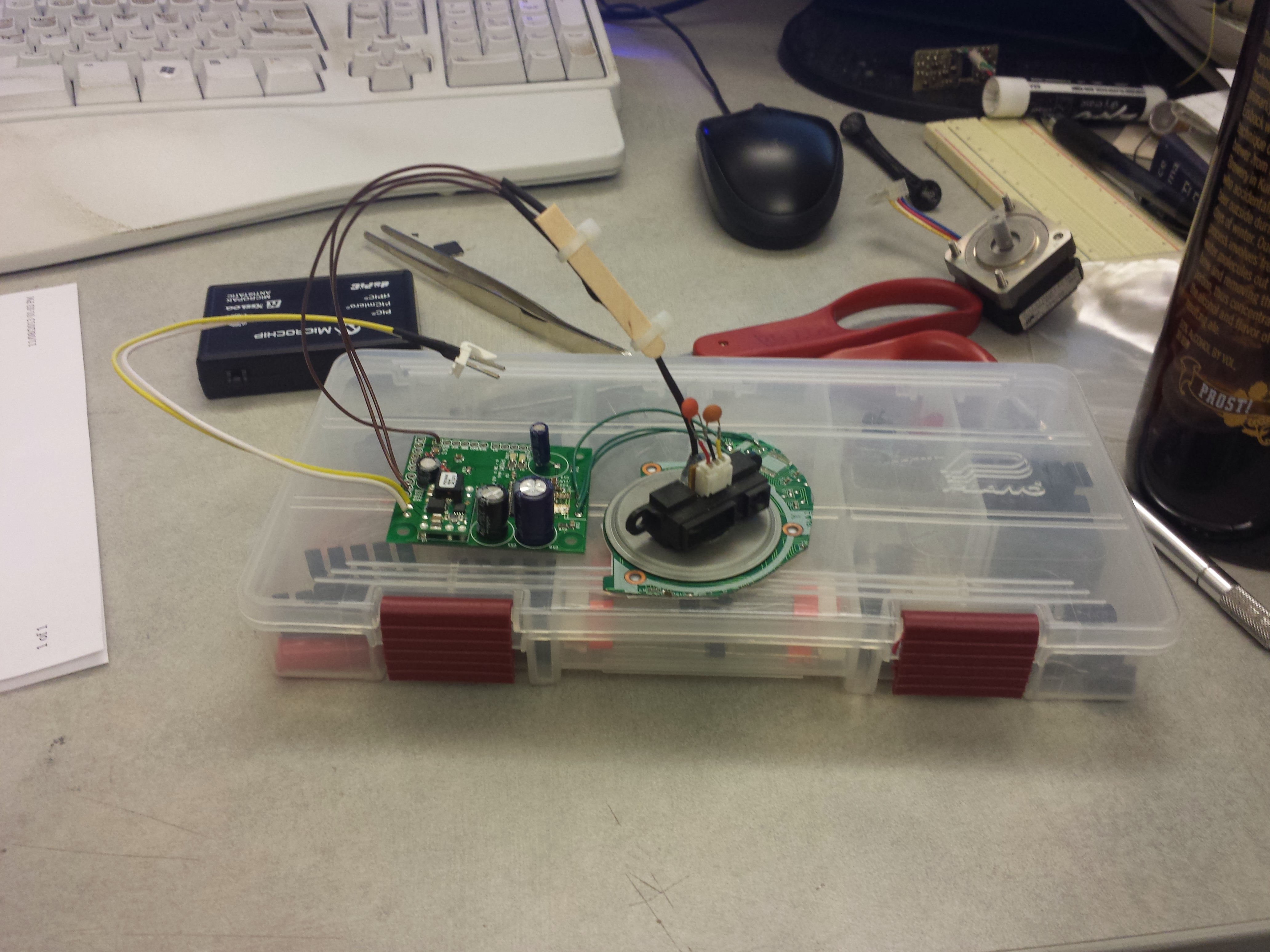
Here was a lesson in hubris and time constraints. During my mechatronics class at UCSC, I decided that I wanted to go above and beyond with my sensor tech by creating a low-resolution LIDAR and integrate some SLAM on my robot. I decided to use one of the small PMSM boards that I designed along with some of the code from one of my brushless stabilization gantries to create a system that allowed for precise aiming of the infrared beam. I used a floppy drive brushless motor as the sensor actuator here.
Here’s a really nice femto-amp leakage current transimpedance amplifier that I made for some micro-pore experiments. I learned that sometimes writing documentation isn’t enough and that often, just because you make a tool for someone, they often times won’t use it if it requires a non-zero amount of integration effort on their side. Also, I learned that femto-amps are really, really small, and that measuring and validating a design with such extreme requirements on leakage current is pretty hard to do correctly.


I’ll finish this post soon, maybe.